Scenario A: Spacecraft Maneuvering
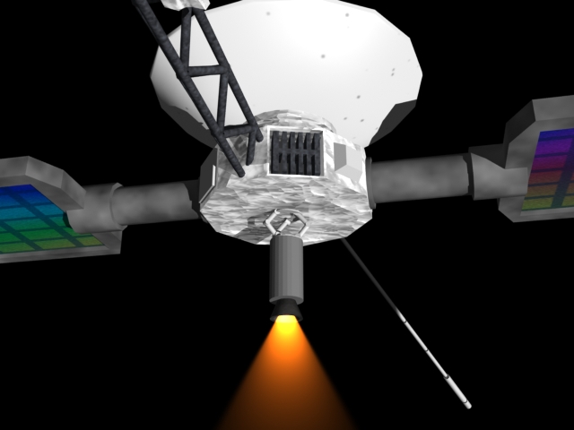
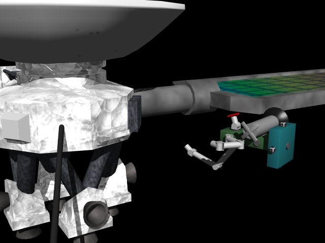
Following a launch vehicle upper stage failure, a critical space asset is stuck in an incorrect orbit. A MORPHbot with a high-capacity maneuvering stage is dispatched to transport the spacecraft to its operational orbit. The scenario is shown below (click on any of the pictures below for a larger image).
|
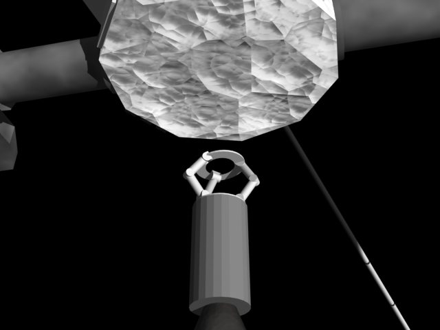
Three robotic manipulators are configured in a Stewart platform configuration, allowing the MORPHbot to approach and capture the wayward satellite. |
|
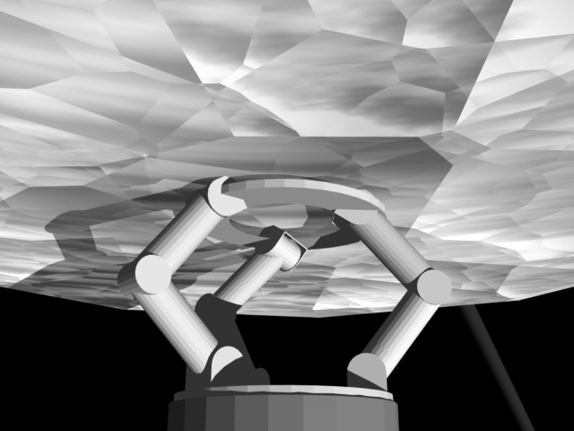
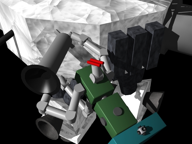
End effectors on the Stewart platform arms grasp hardware artifacts to be used for the contingency reboost. Each arm could be equipped with unique grasping mechanisms pre-selected for specific sites, or an assortment of end effectors could be flown to allow alternatives in the event that the actual spacecraft is different from the as-built drawings. |
 |
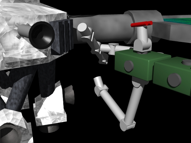
Once in position, the MORPHbot fires its rocket to reboost the satellite or maneuver it to another position in space. Due to the dexterity and control bandwidth of the MORPHbot hardware, the Stewart platform can be used during boost to perform fine adjustment of the line of thrust, controlling spacecraft pointing by direct thrust vector control. |
Scenario B: On-orbit Modifications of Existing Spacecraft
An existing space asset needs to be modified so that Orbital Express or a follow-on system can refuel it. A MORPHbot unit is attached to a maneuvering spacecraft bus, and launched with an upgrade package to allow routine on-orbit servicing. The scenario is shown below (click on any of the pictures below for a larger image). An animation showing part of this scenario is available as a 640x480 20 Mb AVI or a 640x480 13 Mb QuickTime.
|
A free-flight pack is mounted to the back of a MORPHbot node, which has two 6-DOF arms along with a 6-DOF grapple arm. This allows the MORPHbot to approach and grapple to the satellite in need of retrofitting. |
|
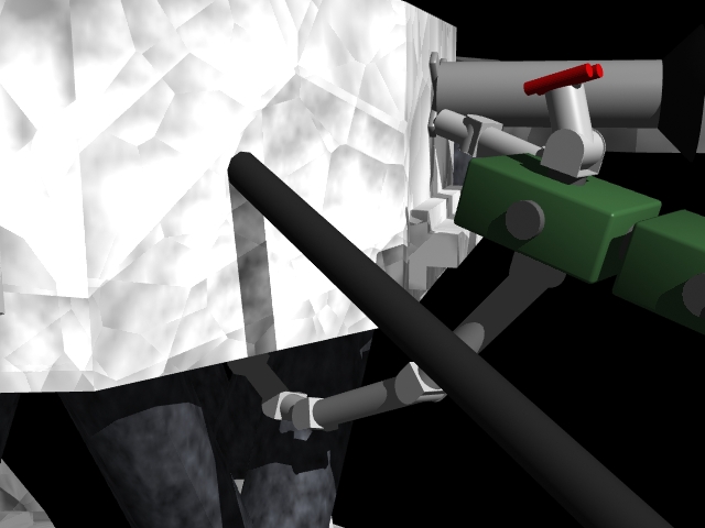
The MORPHbot uses its grapple arm to hold onto the satellite while its 2 6-DOF manipulators retrofit the satellite with the Orbital Express (OE) docking interface. |
|
To make the OE interface functional, hydrazine lines have to be routed and attached to the target spacecraft ground fill & drain ports. Mechanically docking to the OE interface, the MORPHbot right arm removes the left arm and attaches it to the end of the grapple arm. This creates a 12-DOF servicing arm. This longer arm allows the MORPHbot to route and install the plumbing while remaining rigidly docked. |
 |
The longer arm may also be used as an extended grapple arm, allowing the MORPHbot to move to other areas of the spacecraft, while avoiding grapple arm contact with spacecraft appendages. |
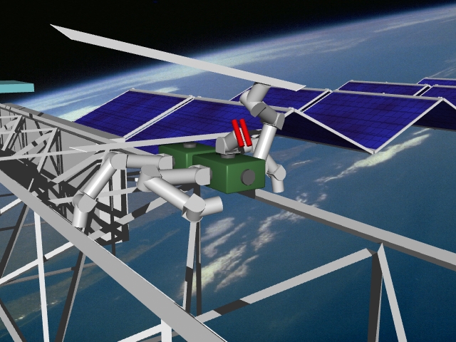
Scenario C: Large Platform Inspection and Maintenance
A space platform, consisting of large-aperture antenna or optical surfaces and associated spacecraft support systems, has to be assembled, maintained, and periodically upgraded. An extensive MORPHbot depot is part of the initial assembly system, and after reaching initial operational capacity, is used to maintain and modify the platform. A simple two-armed inspection MORPHbot is sent on a periodic inspection task, to autonomously scan for micrometeoroid and orbital debris damage. The scenario is shown below (click on any of the pictures below for a larger image). An animation is also available as a 640x480 108 Mb AVI, a 320x480 42 Mb AVI, a 640x480 56 Mb QuickTime, or a 320x480 7 Mb QuickTime.
|
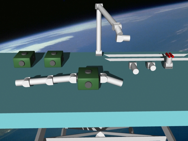
An inspection MORPHbot (two 6-DOF arms with a 2-DOF camera module) walks along a space structure inspecting the beams. The robot notices that a beam in the structure has been damaged, and sends a command back to the MORPHbot assembly/disassembly depot, requesting a robot be built that can carry out a replacement beam. |
|
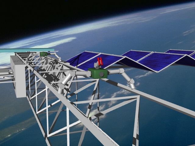
The assembly/disassembly depot plans the optimal configuration for a MORPHbot which will transport the replacement part and combine with the inspection robot to perform the replacement operation. The transportation MORPHbot is assembled and functionally tested in the depot, and sent out along with a replacement beam. |
|
The transportation robot walks out along the beam and attaches itself to the back of the inspection robot. The transportation robot becomes a stable base for a new aggregate MORPHbot, allowing the two arms of the inspection unit to switch end effectors and become servicing arms for the beam replacement task. |
|
Following the successful completion of the truss repair, the transportation MORPHbot returns to the assembly area to be disassembled, making its component modules available to be reconfigured into different robots. The inspection robot continues along its initial assignment, inspecting the rest of the structure. |

© 2003- Space Systems Laboratory
last updated: