Ranger dexterous manipulator specification sheet
28 June 2002
The team has put together a specification sheet on the Ranger dexterous manipulator. Click on the picture below to load the specification sheet.
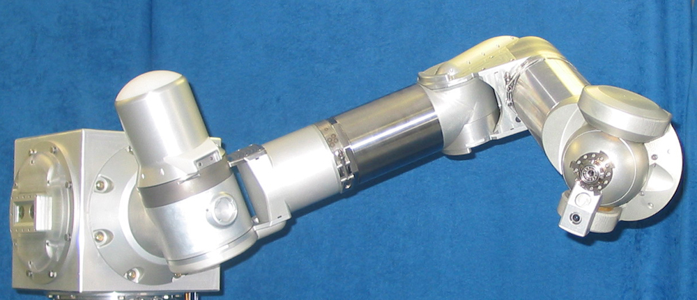
Click on the picture to load the specification sheet (1.9M PDF)
Ranger dexterous arm featured in the June 2002 issue (page 30) of Military & Aerospace Electronics
10 June 2002
(copy courtesy of Robert Renshaw of Payload Systems Inc.)

Click on the picture for a larger image (378K)
Simulated Hubble Space Telescope Electronics Control Unit task
23 May 2002
(update by Brian Roberts)
An attempt was made to perform portions of the removal and replacement of a Hubble Space Telescope (HST) electronics control unit (ECU).
Three ECUs are found on the Telescope as part of the rate gyro assembly. Each ECU enclosure measures 11" x 9" x 7.5" and the unit weighs 17.4 pounds. The ECU is secured inside HST by four keyway slot bolts and one connector drive mechanism. Removal of the ECU is accomplished by backing off these bolts six turns, unfastening the connector drive mechanism on the bottom of the ECU, and maneuvering the ECU off of the keyway slot bolts. The replacement ECU is then installed into its mounting position on the keyway bolts and the connector drive mechanism is fastened. The four keyway bolts are then tightened to approximately 5 ft-lbf. EVA tether loops are provided for retention during on-orbit change out. Two ECUs were replaced on HST during a visit by astronauts during the first servicing mission in December of 1993.
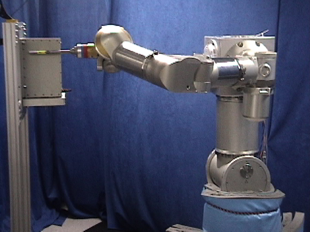
Below are pictures of the Ranger engineering arm performing parts of the ECU removal task and an estimate of how long that part of the task would take. First, the arm (without an end effector) moves back to get the bare bolt drive which is mounted on a tool post. Once the wrist docks with the bare bolt drive, the wrist rolls to remove the bare bolt drive from the tool post. With the bare bolt drive attached to its wrist, the arm moves to one of the ECU keyway slot bolts. After turning the bolt, the arm moves away from the bolt, moves to another bolt, turns it, and repeats the process for the two remaining bolts. The arm then docks with a tool post which allows the removal of the bare bolt drive. The wrist moves to another tool post, "docks" with the right angle drive, and after the wrist rolls to attach the right angle drive to the wrist, the arm moves to the connector drive mechanism at the bottom of the ECU. While this is happening, a second arm would move to a third tool post to remove the tether loop gripper. After the "fingers" of the tether loop close around the tether loop on the ECU, the right angle drive on the other arm drives the connector drive mechanism which starts to lift the ECU out of its fixture.
A video of parts of this task appears below under the May 10th update.
| Task | Time | |
|
|
Attach bare bolt drive to arm | 2:00 |
| Move arm (with bare bolt drive) to ECU | 0:55 | |
| Place bare bolt drive on lower left bolt | 0:51 | |
| Turn lower left bolt 6 times | 0:48 | |
| Move arm from lower left bolt to upper left bolt | 0:51 | |
| Turn upper left bolt 6 times | 0:48 | |
|
|
Move arm from upper left bolt to upper right bolt | 1:13 |
| Turn upper right bolt 6 times | 0:48 | |
| Move arm from upper right bolt to lower right bolt | 0:59 | |
| Turn lower right bolt 6 times | 0:48 | |
| Move arm from lower right bolt to tool post | 1:10 | |
| Attach right angle drive to arm | 2:00 | |
|
|
(Attach tether loop gripper to other arm) | 2:00 |
| Move arm (with right angle drive) to connector drive mechanism | 0:57 | |
| Close tether loop gripper on tether loop | 0:28 | |
| Place right angle drive on connector drive mechanism | 0:39 | |
| Unfasten connector drive mechanism to lift ECU | 0:20 | |
| (Open tether loop gripper from tether loop) | (0:12) | |
| Total time | 17:35 |


2002 IEEE International Conference on Robotics and Automation presentations
15 May 2002
Two papers were presented at the 2002 IEEE International Conference on Robotics and Automation that was held in Washington, DC the 11th through the 15th of May. The first paper, "Effects of Time Delay on Telerobotic Control of Neutral Buoyancy Vehicles," (paper (1.2M PDF)) was presented by Dr. Corde Lane. The paper was written by Dr. Lane, Dr. Craig Carignan, Brook Sullivan, Dr. David Akin, Teresa Hunt, and Rob Cohen. The presentation (presentation (3.9M PDF)) included four video clips which appear below (click on the pictures to start the videos).
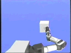
Manipulation task - replacement box change out This video clip shows two experienced test subjects using Ranger Neutral Buoyancy Vehicle I to perform insertions and extractions of the orbital replacement unit fluids box with 0 and 3 second time delay. |
Peg and hole simulation This video shows a subject successfully compensating for the largest fixed error treatment. Although the fixed error can cause large deviations between the commanded and actual displays, that deviation does not change. Therefore, the subjects were able to learn how to compensate and complete the peg-in-hole task with minimal extra effort, even with a three second time delay. |
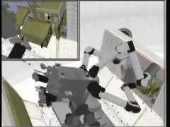
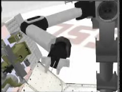
Simulation future work The new graphical simulation uses higher fidelity texture mapping to produce a more realistic virtual environment. These simulations will allow testing with multiple arms. The smaller window in this video clip shows the simulated camera output from the video manipulator. Here the operator controls both the video manipulator and the dexterous manipulator to extract a mock-up of the Hubble Space Telescope electronics control unit. Towards the end of the clip, tracking mode is used by the operator to allow the video arm to follow the dexterous arm. |
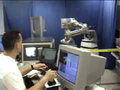
Ranger II Operations An experienced operator control the dexterous manipulator using two three degree of freedom hand controllers. This new 8-DOF manipulator will allow the study of performing tasks with time delay. |
The second paper, "A Skew-Axis Design for a 4-Joint Revolute Wrist," (paper (1.2M PDF)) was written by Drs. Carignan and Howard. The presentation (presentation (3.4M PDF)) included five video clips that appear below (click on the pictures to start the videos).
|
Inverse kinematics modes |
Joint limit avoidance |
Singularity avoidance (simulation) |
Singularity avoidance (experiment) |
|
This video clip exhibits roll, pitch, and yaw motion for two inverse kinematics modes for the wrist. The first mode is 4-DOF control with self-motion. It uses a generalized pseudoinverse method with a self-motion component for avoiding singularities and joint limits. The second mode uses 3-DOF control with independent hand roll. It uses an extended jacobian technique to control tool tip orientation using the first three joint axes and hand roll using a separate command. |
The beginning of the clip shows the arm operating with the 3-degree of freedom (DOF) wrist controller. The arm stops as it hits its yaw limit. After the arm moves away, the 4-DOF wrist controller is turned on causing the pitch housing to be rolled out of the way (without any input from the operator and without the tip of the tool moving). The arm is no able to "push through" the location where it hit the limit with the 3-DOF wrist controller. |
These clips shows the behavior of the wrist as it nears a Type II singularity where all four joint axes collapse into the wrist roll/pitch plane. The tool axis starts out aligned with the pitch axis so that already the wrist is down to 3 degrees of freedom (Type I singularity). As the operator inputs a rotation about the tool axis, the yaw axis starts rotating around to become aligned with the wrist roll/pitch plane, but the wrist roll (forearm) is rotated away before the yaw axis can reach the plane. |
|

The 36th Aerospace Mechanisms Symposium presentation
15 May 2002
Dr. Russ Howard presented a paper, "Design of a Robotic Wrist and Tool-Exchange Mechanism for Satellite Servicing," (paper (3.8M PDF)) at the 36th Aerospace Mechanisms Symposium that was held in Cleveland, Ohio May 14th through the 17th. The presentation (12.4M PDF) included three video clips which appear below (click on the pictures to start the videos).
|
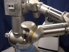
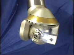
Wrist joint motion This clip shows the 4 degrees of
freedom of the wrist (wrist roll, wrist pitch, wrist yaw, hand roll)
being activated followed by the two tool drive (fast and slow).
The wrist camera and LED can also be seen. |
Joint limit avoidance The beginning of the clip shows the arm operating with
the 7-degree of freedom (DOF) controller. The arm stops as it hits
its yaw limit. After the arm moves away, the 8-DOF controller is
turned on causing the pitch housing to be rolled out of the way (without
any input from the operator and without the tip of the tool
moving). The arm is no able to "push through" the
location where it hit the limit with the 7-DOF controller. |
End effector change out (bare bolt drive) This clip shows
the arm (without and end effector) "docking" with the interchangeable end effector
mechanism, performing a hand roll maneuver, which allows the bare bolt drive to be removed from the tool post. |
Simulated Hubble Space Telescope Electronics Control Unit task
10 May 2002
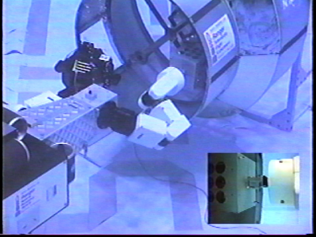
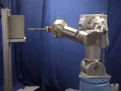
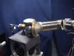
An attempt was made to perform portions of the removal and replacement of a Hubble Space Telescope (HST) electronics control unit (ECU). Below is a video clip of the Ranger engineering arm performing parts of the ECU removal task. First the arm (without an end effector) moves back to get the bare bolt drive which is mounted on a tool post. Once the wrist "docks" with the bare bolt drive, the wrist rolls to remove the bare bolt drive from the tool post. With the bare bolt drive attached to its wrist, the arm moves to one of the ECU keyway slot bolts. After turning the bolt, the arm moves away from the bolt and places the bare bolt drive back on a tool post. Once the bare bolt drive is removed, the wrist docks with and retrieves the parallel jaw mechanism which has a set of "fingers" that fit around the tether loop. The "fingers" are closed around the tether loop as the video ends.
Click on the picture to start the video (3.4M QuickTime)
Engineering positioning leg and dexterous arm from the ground up
3 May 2002
(update by Brian Roberts)
Below is a short video showing the engineering positioning leg, head, and dexterous arm being put together. The video is at five times the normal speed.

Click on the picture to start the video (4.5M QuickTime)
Engineering Arm
Maryland Day Demonstration
27 April 2002
(update by Stephen Roderick)
As part of the campus-wide Maryland Day open house, the engineering arm was demonstrated and ran for approximately 8 hours, non-stop, without a hitch. Control and Actuator power were on the entire time, and the CPUs were never rebooted nor did they ever safe themselves. Motor and electronic temperatures never exceeded 85 degrees C.
At least a couple of dozen people operated the arm. Some of the Ranger team, who have zero or very little experience operating robot arms, managed to lock on to a bolt and undo it. It really is not too bad, once you have the right camera views.
We had one (and only one) observed uncommanded motion. It was a cartesian pitch motion occurring while someone was applying various wrist orientation commands. This occurred near the end of the day. No idea why... it was very brief, it undid itself, and never repeated.
Pictures were taken throughout the day and some of them appear below (click on the picture for a larger image).
|
|
The engineering arm with its tether loop gripper attached to the Hubble Space Telescope Electronics Control Unit |


For more photos of the engineering arm in action, check out the Maryland Day 2002 in the Neutral Buoyancy Research Facility photo archive.
Space Technology Development Center
Open House
Engineering Research Building (near the
College Park Airport)
17 April 2002
3:00 - 5:00p m
(update by Dr. Dave Akin)
You are cordially invited to an open house at the University of Maryland Space Systems Laboratory Space Technology Development Center on Wednesday, April 17th, from 3:00-5:00 pm. The occasion of this event is the completion of the development unit for the Ranger Telerobotic Shuttle Experiment dexterous manipulators. This robotic arm, with eight degrees of freedom and interchangeable end effectors, represents a new state-of-the-art in space flight qualified manipulators; it will be demonstrated in action throughout the open house. Please come join us to celebrate this achievement, and to see the components coming together for the four manipulators that comprise the Ranger Neutral Buoyancy Vehicle II.
The SSL Space Technology Development Center is located on the fourth floor of the University of Maryland Engineering Research Building (previously the Myers Building) next to the College Park Airport. It is only a couple of minutes away from the College Park campus, and easily accessible by car or Metro. Refreshments will be served! Please feel free to contact me for directions, or check the directions below. Also be sure to check out the Space Systems Laboratory web site (http://www.ssl.umd.edu). I hope to see you there!
- Dave Akin
dakin@ssl.umd.edu
Directions to the Engineering Research Building
|
Welcome to the Open House Video
|
Open House Brochure
|


Pictures were taken throughout the day and some of them appear below (click on the picture for a larger image).
|
The EVA Mock-Up greets visitors entering the lobby |
The Ranger Team poses with the engineering PXL and arm
(from left to right: Gardell Gefke, Stephen Roderick,
Marty Devaney, Walt Smith, Eric Rodriguez, Brian Roberts, Dr. Corde
Lane, Andrew Long, Jean-Marc Henriette, Kristin Pilotte, Dr. David Akin,
Dr. Craig Carignan, Steven Weisman, Dr. Russ Howard, and Joe Graves; |


For more photos of the engineering arm in action, check out the Ranger Open House photo archive.
© 2003- Space Systems Laboratory
last updated: